Objective
Project Objective
The objective of this project was to showcase a novel and inexpensive way of using LiDAR technology in a low power, portable embedded system. Using LiDAR technology, a map of a room or multiple rooms could be made automatically by navigating the LiDAR mounted to a robot autonomously without colliding with any obstacles it encounters. As a result, these tasks can be accomplished without any additional sensor feedback and can aid in understanding visually how indoor surroundings look like.
Introduction
Project Introduction
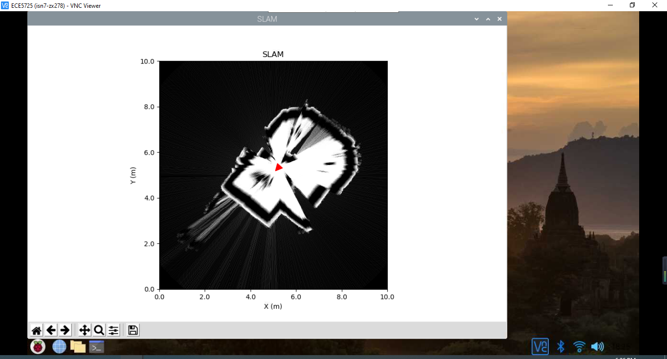
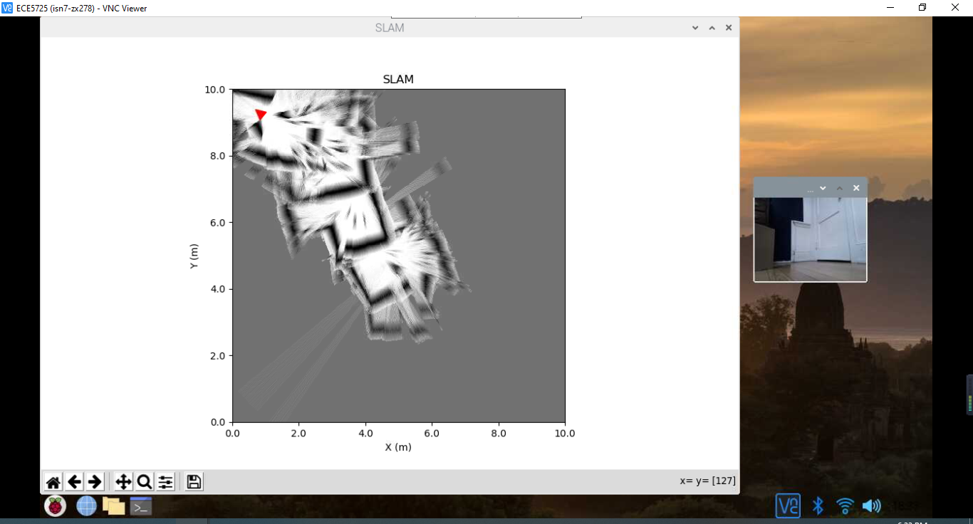
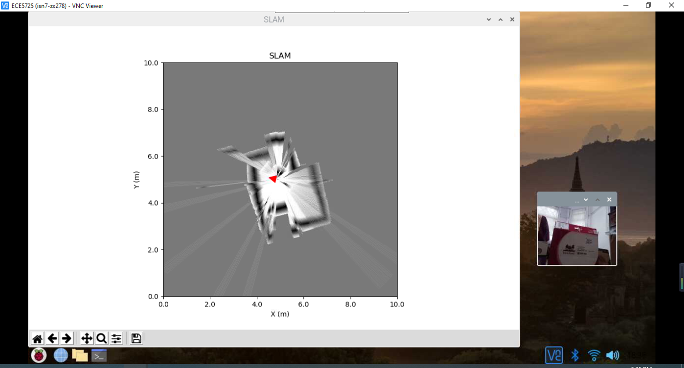
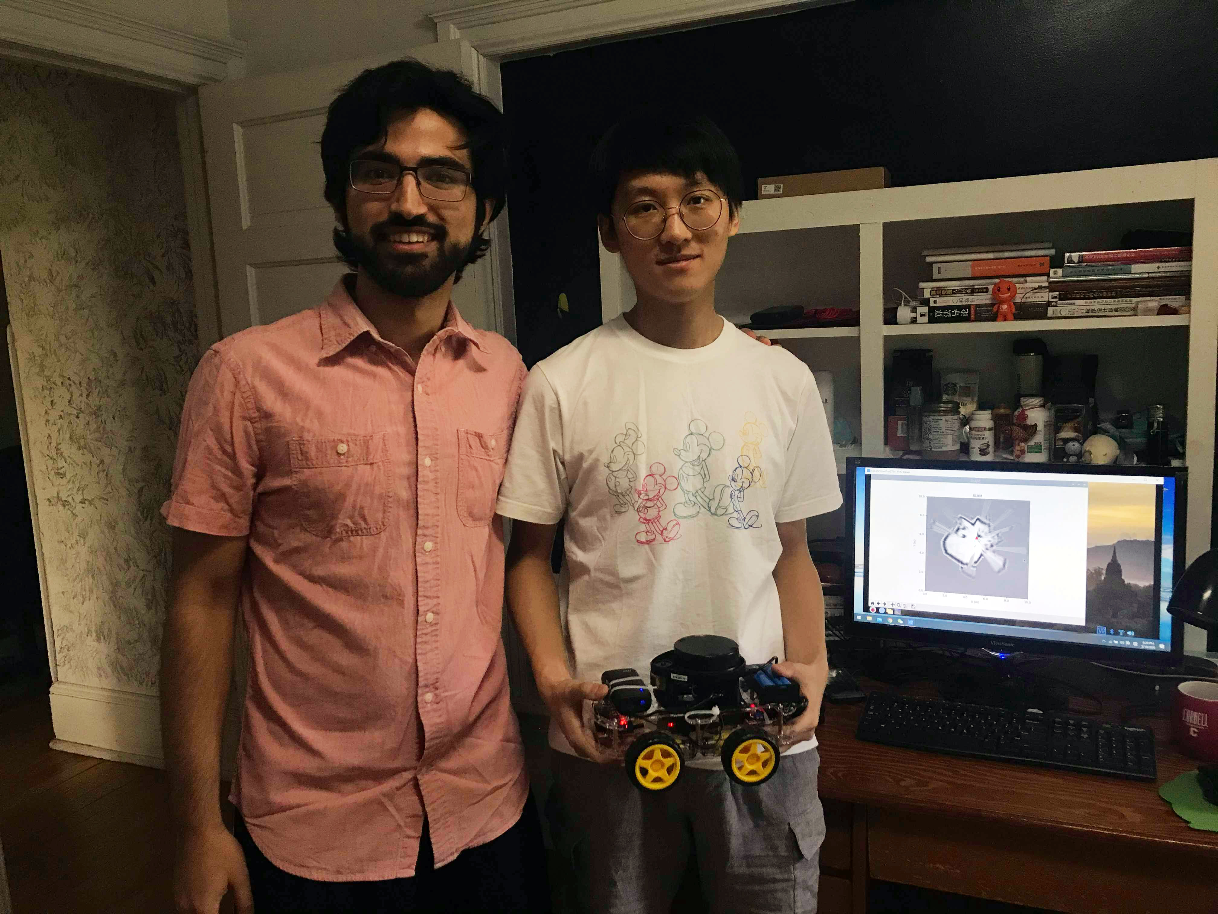
For our final project, we built a LiDAR robot to map a room while avoiding obstacles with autonomous navigation. A Neato XV-11 LiDAR with 360 degrees of freedom was used for sampling data in the form of 90 packets (4 degrees of data per packet) over a serial interface using an Arduino Pro Micro controller to retrieve serial data from the Neato LiDAR’s 4-pin JST serial connector (Rx, Tx, Vcc, Gnd) through a microUSB-to-USB connection to a Raspberry Pi (RPi). An RC car kit with 4 motors was driven by the RPi’s hardware pulse-width modulation (PWM) signals for each side of the RC car to navigate around a room and avoid obstacles using sampled LiDAR data. A visual map of the room was created using a simultaneous localization and mapping (SLAM) algorithm.
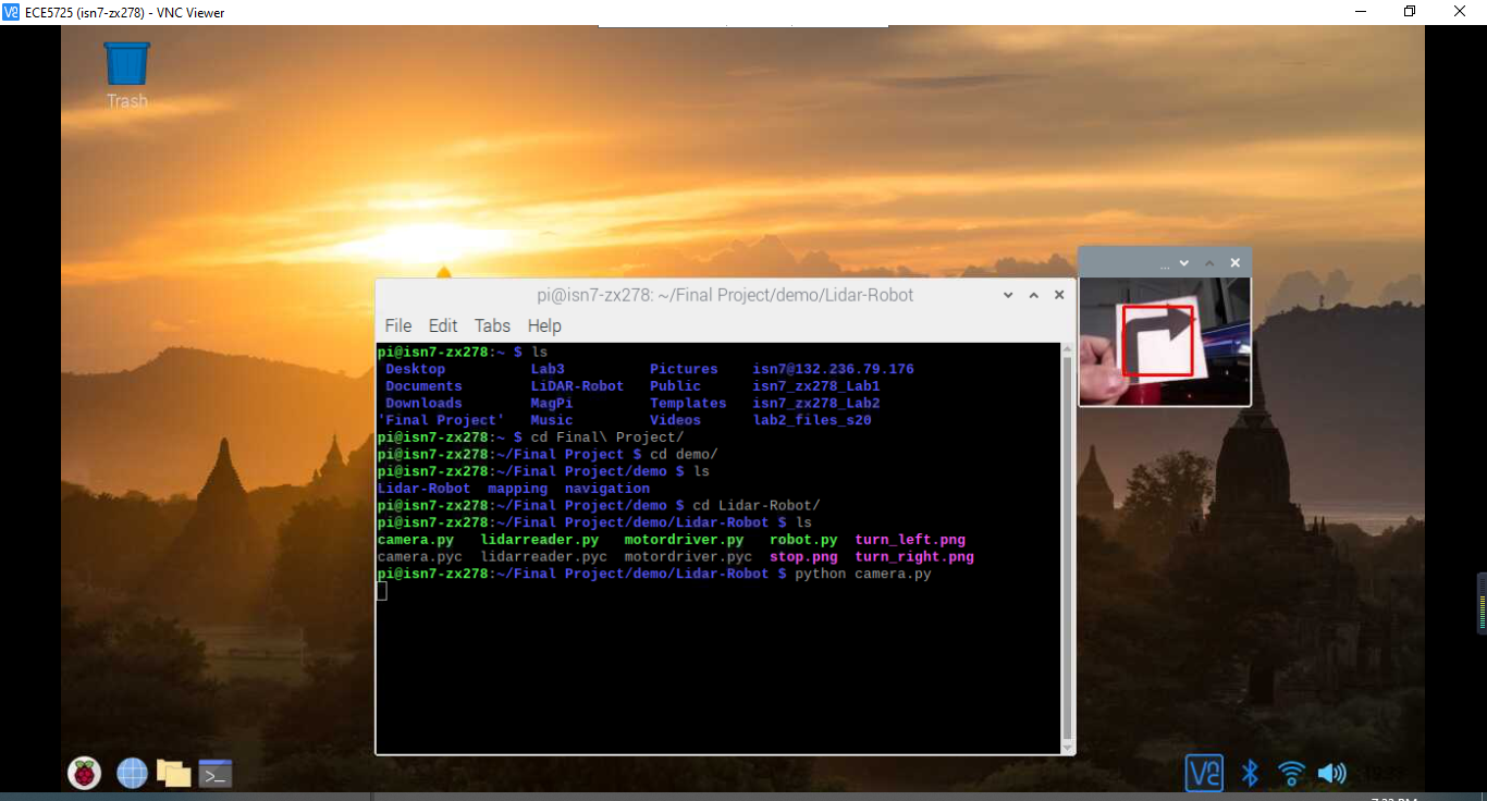
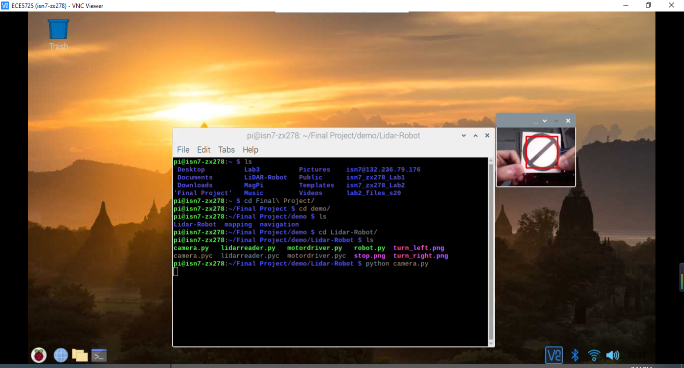
All source code was developed in Python 2.7 using multiple processes and threads for handling several tasks simultaneously. A Raspberry Pi camera is used to receive a visual robot perspective of the room as it navigates. A portable battery pack supply was used to power the RPi, and a separate battery supply was used to power the LiDAR to avoid powering it directly from the RPi for rotation reliability.
- Navigates and avoids obstacles
- Maps the nearby surroundings
- Records a perspective view of the surroundings and recognize traffic signs
Design
Some insights about Design
Hardware
Robot Overview
The general layout of our lidar robot. The battery in the front is to power Raspberry Pi
Robot Layout
The top view of our lidar robot. The battery is to power lidar and motor drivers
Motor Drivers with Prototyping Board
Prototyping Board connects those motor drivers with Raspberry Pi
Second Layer Overview
The second layer of our lidar robot. Motor Drivers connect to Raspberry Pi
Software


Testing
Testing Strategy
Results
Robot test Results

Conclusion
Project Conclusion
Future Work
Work in the future
Work Distribution
Work Distribution


| Specific Task | Team Member(s) |
|---|---|
| Hardware PWM Initial Testing and Implementation on Lab3 robot | Iman Nandi |
| Initial Serial Tests on Arduino Software | Iman Nandi |
| Create motordriver.py to control L298N motor drivers | Zihao Xue |
| SLAM Algorithm Package Configuration | Iman Nandi |
| Serial Data Analysis and Conversion in Python | Zihao Xue, Iman Nandi |
| Serial Data Performance and General Software Debugging | Zihao Xue, Iman Nandi |
| Create robot.py, lidarreader.py and design interfaces for SLAM Algorithm Package | Zihao Xue |
| Threading, Multiprocessing, and Software Class Organization | Zihao Xue |
| Camera Programming | Zihao Xue |
| Final Robot Hardware Setup | Zihao Xue, Iman Nandi |
| PWM Parameter Tuning and Camera Testing | Zihao Xue, Iman Nandi |
Budget
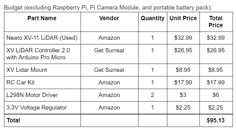
Project Budget
References
References
Code Appendix
Code Appendix
'''
robot.py - Python code for final project demo
Author: Zihao Xue

'''
import numpy as np
import threading
import time
from lidarreader import lidarReader
from motordriver import MotorController
from roboviz import MapVisualizer
from breezyslam.algorithms import RMHC_SLAM
from breezyslam.sensors import XVLidar as LaserModel
from multiprocessing import Process, Queue, Value, Lock
from camera import Camera

MAP_SIZE_PIXELS         = 500
MAP_SIZE_METERS         = 10

class Robot:
  def __init__(self, messagequeue):
    # Connect to Lidar unit
    # when initializing the robot object, we first open lidar and start
    # reading data from the lidar
    self.lidar = lidarReader('/dev/mylidar', 115200)
    self.mover = MotorController()

    # Create an RMHC SLAM object with a laser model and optional robot model
    self.slam = RMHC_SLAM(LaserModel(), MAP_SIZE_PIXELS, MAP_SIZE_METERS)
    # Set up a SLAM display
    self.viz = MapVisualizer(MAP_SIZE_PIXELS, MAP_SIZE_METERS, 'SLAM')
    # Initialize empty map
    self.mapbytes = bytearray(MAP_SIZE_PIXELS * MAP_SIZE_PIXELS)
    self.messages = messagequeue

    # All the functions should run in the same process so that the variable can be shared
    self.thread = threading.Thread(target=self.navigate, args=())
    # the main-thread will exit without checking the sub-thread at the end of the main thread.
    # At the same time, all sub-threads with the daemon value of True will end with the main thread, regardless of whether the operation is completed.
    self.thread.daemon = True
    self.navigating = True
    self.thread.start()

  # Construct Map should always run in the main process
  def constructmap(self):
    while True:
      time.sleep(0.0001)
      # Update SLAM with current Lidar scan, using first element of (scan, quality) pairs
      self.slam.update(self.lidar.getdata())
      #print(self.lidar.getdata())
      # Get current robot position
      x, y, theta = self.slam.getpos()
      # Get current map bytes as grayscale
      self.slam.getmap(self.mapbytes)
      # Display map and robot pose, exiting gracefully if user closes it
      if not self.viz.display(x/1000., y/1000., theta, self.mapbytes):
        break

  def navigate(self):
    while self.navigating:
      time.sleep(0.01) # (yield) allowing reading data from the serailport
      if(self.messages.empty()): # The camera doesn't detect one traffic sign message.empty()
      #if(True): # The camera doesn't detect one traffic sign message.empty()
        front_too_close, left_too_close, right_too_close = False, False, False
        if(self.lidar.angle_180 < 400):
          front_too_close = True
        left_angle = np.argmin(self.lidar.left_container)
        right_angle = np.argmin(self.lidar.right_container)
        if(self.lidar.left_container[left_angle] < 250):
          left_too_close = True
        if(self.lidar.right_container[right_angle] < 250):
          right_too_close = True
        if(front_too_close and left_too_close and right_too_close):
          self.mover.backward()
        elif(front_too_close):
          if(self.lidar.angle_270 > self.lidar.angle_90):
            self.mover.turn_left()
          else:
            self.mover.turn_right()
        elif(left_too_close or right_too_close):
          if(left_too_close):
            self.mover.turn_right(left_angle)
          else:
            self.mover.turn_left(right_angle)
        else:
          self.mover.forward()
        #print(self.lidar.left_container)
        #print(front_too_close, left_too_close, right_too_close, self.lidar.angle_180)
      else:
        sign = self.messages.get() # get the detection id
        if(sign == 1):
          self.mover.stop()
        elif(sign == 2):
          self.mover.turn_right()
        else:
          self.mover.turn_left()


if __name__ == "__main__":
  running = Value('b', True)
  # multiprocessing communication channel between processes
  messagequeue = Queue()
  # multiprocessing required classes
  camera = Camera()
  robot = Robot(messagequeue)
  # processes
  pro1 = Process(target=camera.recording, args=(running, messagequeue,))
  pro1.start()
  #pro2.start()
  robot.constructmap()
  # Wait for the process to safely exit
  pro1.join()
  #pro2.join()
  robot.navigating = False
  robot.thread.join()
  robot.mover.shutdown()
  print("safely exit")